Results 1 to 14 of 14

Thread: adding electric fan

Hybrid View

  1. #1

    Array
    Status
    Offline
    Join Date
    10-29-2014
    Posts
    1,279
    Location

    Earth, the Solar System
    Vehicle

    1985 Dodge Ram 50
    Engine

    G63B

    adding electric fan

    You can probably figure out how to do this yourselves. But if you are like me and need examples here ya go. TLDR- Get fan, get wiring temp switch kit, install.

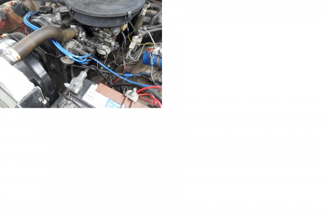
    You can get relay kits with a grounding temperature switch for the fan very easily these days. So the real problem is getting a fan and installing it. I paid to get an OE thermostat housing* so I could put the sensor in it. You can also get those kits with a hose fitting for the top rad hose, to screw the temp switch into.

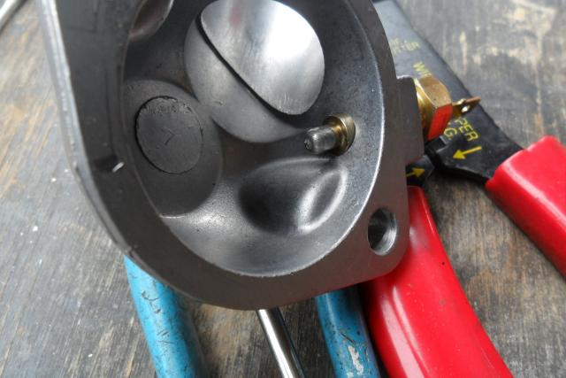
    *The OE Tstat housing has the wrong threads for 1/8NPT temp switch that came with the wiring kit. You can choose what size and temp range the switch is and the American Volt kit comes with simple instructions and a diagram. I wanted it to be after the Tstat. I had to drill and tap. Turned out to be very easy using a bench vise 21/64" bit that didn't really touch the existing threads but did remove the shoulder the manufacturing process left at the end of the hole. Then I ran a 1/8NPT tap in to it horizontally using a couple drops of oil for the whole cut. Cutting two turns then taking it out to clean up the chaff. I went far enough in when I screwed the temp switch in the tip was just showing inside. New gasket and a little permatex and bolted on my new thermostat housing.

    The model number on this fan is #35317 by Standard (Four Seasons). This one has an NLA plug on it so you can't get a dongle, you have to cut the plug off the fan and use wire connectors. #10 wire. Using Dorman Fully Insulated Disconnects 86429 so you can remove it w/o cutting wire. Black is ground. The other two are low and high speed. I just folded low one up and taped it so it is out of the way and am using the High speed side. I used jumper wire from battery to figure out which one was which. I will eventually add a cheap off on switch so I can run it at will or if the temp switch fails. When it came on after I had it installed it was louder than I expected. Maybe low speed would have been enough. It only ran a couple of minutes and went off again.

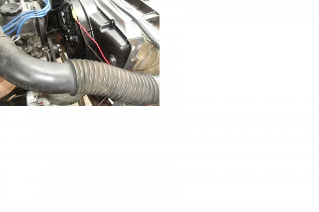
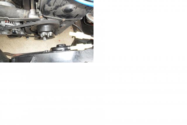
    You will have to use some kind of spacer behind the nuts to hold the fan pulley on. I used 3 flat washers. I may end up removing one flat and put a lock washer to replace it. You will also have to cut bits off the fan built in shroud if you use a Ford fan. It is mounted to the OE shroud holes on the rad. I did not take picture before installing it. You need to cut out for the lower hose. I used self sticking weather strip where it is in contact with the rad and for the cutout by the lower hose. The fender washers on the passenger side also have a rubber gasket under them which I made from some rubber sheet I have.

    * If you have heard about using Ford fans from the late 80's early 90's, be careful which one you buy. This fan was a size mistake (seller not me, I kept it to do this.) for my other rig and made me look harder. Turns out they are almost a different size for every year and in the same year for different motor options (dual or single cam) on the same car! By the way the sizes listed for Four Seasons fans are counting those ears that stick out it is not the edges of the built in shroud as you might expect it to be.

    Let me know if I forgot to explain anything. Like draining the radiator into a bucket before disconnecting anything. The system won't let me add the other pictures. ?? It doesn't say why. EDIT- I think I figured it out they were all over 2mb

    The shoulder removed. Shiny
    Fan Mount on driver side
    Fan Mount Passenger side
    Attached Images
    Last edited by 85Ram50; 06-26-2024 at 05:26 PM.

  2. #2

    Array
    Status
    Offline
    Join Date
    10-29-2014
    Posts
    1,279
    Location

    Earth, the Solar System
    Vehicle

    1985 Dodge Ram 50
    Engine

    G63B
    Update- The fail safe is that the temp switch grounds when it fails so that the fan runs continuously. I had the temp switch fail on my other truck. Seller is sending me a new switch.

  3. #3

    Array
    Status
    Offline
    Join Date
    06-30-2024
    Posts
    30
    Location

    Cleveland, TN
    Vehicle

    1989 Dodge Ram 50
    Engine

    G63B
    Hey, this write up is super useful, not very much elaboration on the electric fan convert anywhere else on the sub.

    What temp switch kit did you end up using? Also, have you had any issues running this fan on the stock alternator that came with the G63B? Let us know, thanks.

  4. #4

    Array
    Status
    Offline
    Join Date
    10-29-2014
    Posts
    1,279
    Location

    Earth, the Solar System
    Vehicle

    1985 Dodge Ram 50
    Engine

    G63B
    Quote Originally Posted by Tonka View Post
    Hey, this write up is super useful, not very much elaboration on the electric fan convert anywhere else on the sub.

    What temp switch kit did you end up using? Also, have you had any issues running this fan on the stock alternator that came with the G63B? Let us know, thanks.
    Sorry man I do not come here as often as I used to. Well the kit company ghosted me after telling me they were sending a new grounding temp sensor. It was American-Volt address in Denver but the kit is obviously Chinese.

  5. #5

    Array
    Status
    Offline
    Join Date
    10-29-2014
    Posts
    1,279
    Location

    Earth, the Solar System
    Vehicle

    1985 Dodge Ram 50
    Engine

    G63B
    I put in a manual switch for the fan in that other truck I mention above. My question is at the end of this longish post I prewrote.

    New Question
    OK I decided I needed a remote switch for my electric fan. I put the wire from the grounding temp switch through to the cab and grounded the other wire on the switch and got nothing. I gave up due to rain. Today I notice my wire from ignition on source to relay was disconnected. I reconnected it using new crimp & shrink. It is spliced with the fuel pump ign on wire into the black red stripe wire that is hot with key on. The fan worked when first installed when it got up to temp. Grounding temp sensor is in the thermostat housing. Seems like the thing making me think I needed a manual switch was the disconnected wire but since i was there and have the wires run.....
    I checked voltage on the pins in the relay with key on with the HF multimeter set at DC 20
    They were Pin 30- 12v+ pin 85-0 Pin 86 -10.2v Pin 87-0
    I checked the voltage at the grounding temp sensor and it was 1.3v. Inside the cab the wire on the switch from the temp sensor was the same. I grounded it in a couple places inside the cab no luck. I grounded it with the jumper cable from the neg post of the battery no luck. I haven't let it run to get hot to test if it will work normally because it is on jack stands with the driveshaft out, it is cool out and it is raining off and on. I'd like to know if anyone can give me guidance to determine if the switch is bad out of box, the relay is bad or what I am doing wrong.
    I watch this guys vid to recheck my work, but I bought the kit off ebay it has nothing to do with him. https://www.youtube.com/watch?v=9Hj7Ri3TXhc

  6. #6


    Array
    Status
    Offline
    Join Date
    03-06-2018
    Posts
    653
    Location

    Tucson, AZ USA
    Vehicle

    1987 Dodge Ram 50
    Engine

    G54B
    Typically relay terminals would be connected like so:

    30: To battery (+) terminal;
    85: To ground;
    86: To switch (e.g. key-on power in your case);
    87: To device (e.g. rad fan in your case).

    Lowish voltage at 86 is NBD cos it only needs enough microcurrent to trigger the relay. With power from the battery good at 30, power applied to 86, and a good path to ground from 85, there should be ~12 VDC at 87. Since your 87 reads 0 with the key on, either the relay is bad or the path to ground from 85 is bad.
    1987 Dodge Ram 50 4G54 RWD longbed ("Elmo")
    1979 Lancia Beta Zagato spider ("Lola")
    1982 Lancia Beta Zagato spider ("Luigi")

  7. #7

    Array
    Status
    Offline
    Join Date
    10-29-2014
    Posts
    1,279
    Location

    Earth, the Solar System
    Vehicle

    1985 Dodge Ram 50
    Engine

    G63B
    Thank You.
    OK Is the breaker directional? I have it set up that 87 (<Should have said 30) runs to the copper pole then the silver pole runs to the pos battery post. I just looked the vid shows that he has it bat to silver etc. If it is not directional then the breaker is bad.
    Ima go switch them and see if it works while I wait.

    EDIT- I changed the wires on the breaker no joy.
    I have
    30 to the breaker and on to the battery. 12v
    85 to the grounding temp switch no voltage or -.01 (I added a wire using a new plug, to run into the cab for the manual switch as in the vid)
    86 is to key on power 10v +
    87 to the fan. no voltage or -.01
    The ground is the non power wire on the fan.
    Last edited by 85Ram50; 10-02-2025 at 08:10 PM.

  8. #8

    Array
    Status
    Offline
    Join Date
    10-29-2014
    Posts
    1,279
    Location

    Earth, the Solar System
    Vehicle

    1985 Dodge Ram 50
    Engine

    G63B
    This morning I tested the fan. It runs. I took the ground off and scraped paint away and cleaned it up put it back. I tested the relay it is good. Resistance is 75ohm, it clicks when power is applied and there is no reading between 30 and 87 when power is applied. I found this vid that tells me I had the breaker wired backwards. https://www.youtube.com/watch?v=emckrqicORs It is directional. The copper pin goes to the battery. I had the key on and put the multi meter on each pole of the breaker and got no reading. ?? How was the pin on the relay hot???
    I sent the people at that web address a note asking if I damaged it since I cannot find anything about how to test it. I have an inline fuse I can install when I find out if it is broken or???. Also apparently it should tell me how many amps the breaker is rated for on it somewhere. I assume that would be the fuse size.

  9. #9


    Array
    Status
    Offline
    Join Date
    03-06-2018
    Posts
    653
    Location

    Tucson, AZ USA
    Vehicle

    1987 Dodge Ram 50
    Engine

    G54B
    Not sure whether a breaker would need to be wired with a certain polarity, as I just use a 10A fuse between the battery (+) and relay 30 terminals.

    85 and 86 can be wired either way around; one to a ground, the other to whatever switched power source should trigger the relay (key-on power in this case). I'm not sure what you mean by saying 85 is connected to a grounding temp switch, as that would mean the relay can never trigger when that switch is open. Typically I just have a short wire from 85 to the screw in the relay's mounting tab, where that screw secured to the body serves as a ground.

    To clarify how a relay works, there's two separate circuits inside: the trigger circuit, and the switched circuit. When the trigger circuit gets power (to 86, thru the relay to 85 to ground), it energizes an electromagnet that closes a switch, thereby completing the switched circuit (connecting power from 30 to 87).
    1987 Dodge Ram 50 4G54 RWD longbed ("Elmo")
    1979 Lancia Beta Zagato spider ("Lola")
    1982 Lancia Beta Zagato spider ("Luigi")

  10. #10

    Array
    Status
    Offline
    Join Date
    10-29-2014
    Posts
    1,279
    Location

    Earth, the Solar System
    Vehicle

    1985 Dodge Ram 50
    Engine

    G63B
    The breaker actually indicates one side for battery (Cu), and one side for aux (silver). It is so tiny I never noticed until I saw that vid.The grounding temperature switch is what turns the fan on by grounding when it reaches the temp it is built for. That is how this fan wiring kit works. The manual toggle switch works by being connected to that wire (85) Actually it is two wire coming out of the female connector that slips over the temp switch and one runs into the cab and I ground the manual switch in there. That is how to bypass the temp switch to ground it and make it run as per that video. It works in my other truck. IDK what is going on here. The battery says it has 12.4v+ I'm taking a break right now.
    I tried clamping the two wires in vice grip that go to the breaker w/o the breaker and it gave no joy. I also tried pulling the female connector off the grounding temp switch and ground it direct on the neg battery cable. with everything else hooked up right, I could hear the relay click but the fan did not come on. The only other thing I can think of is the ground from the fan to the metal body work in front of the radiator or the ground I have inside the cab is bad.

    Edit- Forgot to mention I tested the toggle switch. It did nothing in one position and showed the same number as touching the probes to each other in the other position.
    Last edited by 85Ram50; 10-03-2025 at 01:42 PM.

  11. #11

    Array
    Status
    Offline
    Join Date
    10-29-2014
    Posts
    1,279
    Location

    Earth, the Solar System
    Vehicle

    1985 Dodge Ram 50
    Engine

    G63B
    At the end of the day my multi meter might be defective. Well the pin pulled out of the red probe and was only hanging on by a thread and then a little bit later the back probe just fell off the wire. So some of my readings may have been wrong. That said as I had lay wondering why it would not work it occurred to me this fan may be drawing more power than my system can provide. I have the high speed wire connected on this 2 speed fan. From what I have been able to find out this Ford Taurus fan draws 30A on high speed. I know it worked when I first wired the system and let it idle until it got warm enough to kick on. But I have had electric problems with this truck since I bought it.Even though I have added a 90A alternator with an external regulator. Sometimes I have all the power I need and sometimes I don't. That may be part of my problem. I am going to connect the low speed wire to the power supply and see if that works.

  12. #12

    Array
    Status
    Offline
    Join Date
    10-29-2014
    Posts
    1,279
    Location

    Earth, the Solar System
    Vehicle

    1985 Dodge Ram 50
    Engine

    G63B
    Solved but not solved.
    I went to HF and they gave me new probe wires for the multi meter. I hooked up the low power side of the fan. Tried everything and nothing worked. I started the motor and let it get hot and with the laser thermostat it was at 225 and water was coming out of the overflow and nothing.
    In frustration I went to get a new 5 pin 40A relay, a 40A short stop breaker, and a new toggle switch. I installed them and no joy with the fan. I was standing there trying to fathom why the dam thing would not work when all info I have says it is wired right and mindlessly picked up the black wire with red stripe I have the fan and the fuel pump relay getting ignition power from.
    I moved it toward the cab a couple inches and the fan came on! I shut the truck off and hooked up the high power side of the fan, started up and it ran again. The toggle switch had no effect and the fan seems to want to stay on when the key is on now. The temp at the grounding temp sensor was 125. so not hot enough. I think I posted the temp range I selected for it above.
    This is progress and motivation to try to find a way to rewire my truck. I have nothing to power but the fuel pump, radio, fan, starter, lights and the dash. I don't need these dam wiring harnesses with so many wires I am not using and no way to figure out which one is doing what. So if anyone knows how to wire a 2.0 with just those things I can tear my faulty old wires out and redo it nice and neat. I did trace, re-tape with cloth tape and do a continuity check from the tail lights into the cab a few years ago. If I figure anything else out I will be Bach. :-)

  13. #13


    Array
    Status
    Offline
    Join Date
    03-06-2018
    Posts
    653
    Location

    Tucson, AZ USA
    Vehicle

    1987 Dodge Ram 50
    Engine

    G54B
    Black wire with the red stripe only gets power while cranking the starter. Notice this is (or should be!) connected to the same end of the ballast resistor that the coil is connected to, so this bypasses the ballast during starting to give a bit more oomph to the spark. Weird that simply moving that wire would cause anything to work, so maybe there's a short or break in that wire somewhere?

    Black wire with the white stripe, connected to the other end of the ballast resistor, gets power whenever the key is on, so that's the one you'd want to use for triggering the relay. Having the relay ground thru that temp switch would be correct to run the fan only when that switch closes with the key on; my apologies I hadn't considered that before.
    1987 Dodge Ram 50 4G54 RWD longbed ("Elmo")
    1979 Lancia Beta Zagato spider ("Lola")
    1982 Lancia Beta Zagato spider ("Luigi")

  14. #14

    Array
    Status
    Offline
    Join Date
    10-29-2014
    Posts
    1,279
    Location

    Earth, the Solar System
    Vehicle

    1985 Dodge Ram 50
    Engine

    G63B
    That wire (black red stripe) had power with the key on not cranking when Geezer guided me through figuring out how to power my fuel pump before I got the kit it is running off now. I'm pretty sure something is shorting too.
    Something in the wires is still off since the toggle switch doesn't work. Or maybe the new toggle switch is bad out of box and grounding it? I'll put the old (new also, I changed it just in case) one on just to see, if the fan still runs when I try again. I have two big things to learn this winter, what program to get to design a small building and how to wire my truck from scratch. .
    Last edited by 85Ram50; 10-06-2025 at 05:42 AM.

Bookmarks

Bookmarks

Posting Permissions

  • You may not post new threads
  • You may not post replies
  • You may not post attachments
  • You may not edit your posts
  •