Page 1 of 7 123 ... LastLast
Results 1 to 25 of 154

Thread: The Fear Monger

  1. #1


    Array
    Status
    Offline
    Join Date
    03-16-2011
    Posts
    3,803
    Location

    Sacramento, CA
    Vehicle

    1979 Dodge D-50
    Engine

    Chevy V6

    The Fear Monger

    Extreme Truck Class. D-50 build out. Chevy. 4.3L V6
    After going through the VORRA Rule Book my build falls under the Extreme Truck Class.

    LIVE FIRE??? You missed it. but there is a video on the last posts of the page.
    Lets start out with the live build cam. Here you can look in and see whats going on. I'm usually in the shop after 3:00 Pm Pacific Time.

    Links to parts and things used in the build can be found here.
    http://www.mightyram50.net/vbulletin...-used-in-build


    Attached Images
    Last edited by camoit; 01-24-2023 at 01:13 AM.

  2. #2


    Array
    Status
    Offline
    Join Date
    03-21-2011
    Posts
    767
    Location

    WA
    Vehicle

    1989 Mitsubishi Mighty Max
    Engine

    4G63-T
    Nice looking build thread. You still got time to work on your truck with the board?seems like you did a lot in the past week for the board that's why.

  3. #3


    Array
    Status
    Offline
    Join Date
    03-26-2011
    Posts
    674
    Location

    Stafford, VA
    Vehicle

    1995 Mitsubishi Mighty Max
    Engine

    Chevy V8
    thanks for taking your time for the board. But you can work on your truck too..
    :p we wont get mad at ya.

    Nothing new to the truck lately? either way keep up the great, excellent work

  4. #4

    Array
    Status
    Offline
    Join Date
    04-01-2011
    Posts
    155
    Location

    Garden Valley, CA
    Vehicle

    1990 Mitsubishi Mighty Max
    Engine

    6G72
    Quote Originally Posted by l.k. View Post
    thanks for taking your time for the board. But you can work on your truck too..
    :p we wont get mad at ya.

    Nothing new to the truck lately? either way keep up the great, excellent work
    and keep us updated.

  5. #5


    Array
    Status
    Offline
    Join Date
    03-16-2011
    Posts
    3,803
    Location

    Sacramento, CA
    Vehicle

    1979 Dodge D-50
    Engine

    Chevy V6

    The Start of the build.

    Ok everybody I found an engine and trans for the build out. It's a 97 Chevy 4.3 V6 Vortec, and the trany is a Tremec T56 6 speed. I found a guy on Craigslist that had the engine. Went to there place up in the foot hills. He had a tweeky friend with the trany. The first thing he asked me, "are you a cop" I guess they herd the scanner in my truck. They wanted $1500.00 for the set but, with some negation and them thinking I was a cop. I told them I would give them $450.00 and I would forget what they were cooking in the shed out back. You should have seen the look on there face when I said that. They thought they were going to get busted right there on the spot. But I told them I wasn't a cop until tomorrow morning. They were happy to get me a receipt load the stuff in the back of my truck and get me out of there real fast. Little did they know that I just look like a cop. Or if they would have read the side of the truck they would have see it said On Site Concrete Inc. with a phone number. Here is a pict of the parts. You just got to love a tweeker.

    engine_trans_befor.jpg

    Fri Feb 26, 2010 6:27 pm
    Over came a large hurtle today. I went to the California DMV. Now in California there is a law called AB100 It lets 500 cars per year be registered by either the year of the engine or the body type. They normally are gone on the first day of the year by around 11Am. These things are like gold. I Once I found out that there was 150 left I new I had to have one to build the truck the way I wanted to. So I went to the DMV in Carmichael, what a joke that is. One hour in line just to get a bingo ticket. Then 2.5 hours to get to the person at the counter. Then they wanted to see the truck. I told them how can you see a truck if you drive it here to show them. Now I know that in talking to the department that gives this “paper of gold” out I can get it with out the truck. But they were stuck on stupid. I herd that the Folsom office knows how this works. So off I went. With an engine receipt and a junk slip for one of the trucks I have. After 4.5 hours there I had what I came for. Now the rules are simple. Have all the receipts you used to build the truck, OR build a car from a junked car but it can’t look like the car you junked. But when they ask you is the truck complete tell them YES, but it is at home. As for a price I gave them a round about cost of $13000.00. After a fee of $260.00 I’m now the proud owner of a constructed truck. Now to build the truck. Then there is the CHP,

    Dmv_outside.jpg Dmv_doorway.jpg


    Well I just scored a frame from the neighbor behind me, Phil. He is a hot rod guy and has a 1932 Ford, real nice car he has put many hours in to it. I’ll get a pict up of it when I can. Well anyway he just gave me a 1996 Chevy Caprice frame it has 4 wheel disk brakes that came stock for the California Highway Patrol. So it looks like I have a new used front spindles and rear end. The rear end on the D-50 is 48 inch wide when measured from backing plate to backing plate. The Chevy is 56 inch so I will need to find some offset rims or do something to keep the truck some what stock looking. Well here is a pict what the ride height that I'm shooting for. Give or take 3 inch. If I can get a 6 inch suspension drop and a 10 up travel fo a total of 16 inch travel I will be satisfied. NOTE the two 4 X 12 blocks under the cab. This puts the bottom of the cab at the height of the stock bed. Now it's time to start building the roll cage frame


    ride_heigtht_2238.jpg
    Last edited by camoit; 06-09-2019 at 04:17 PM.
    Members come and members go, But the board keeps track of them.
    Find me on FaceBook
    clicking HERE.

    Or look on YouTube Click Here.
    http://mobilemillwright.com

  6. #6


    Array
    Status
    Offline
    Join Date
    03-16-2011
    Posts
    3,803
    Location

    Sacramento, CA
    Vehicle

    1979 Dodge D-50
    Engine

    Chevy V6
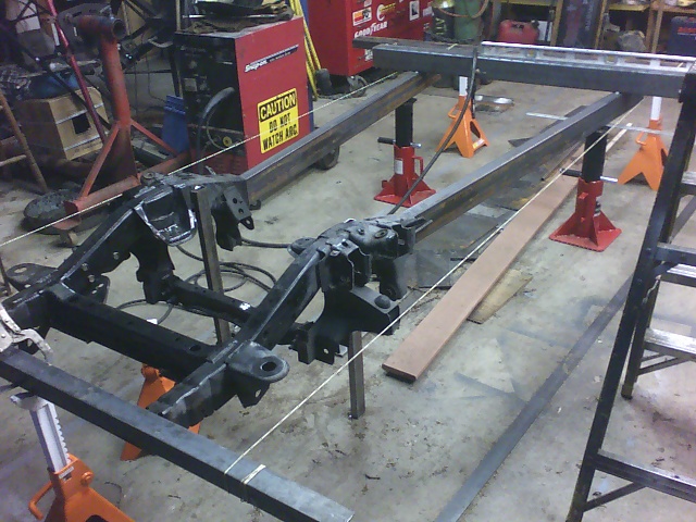
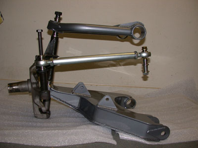
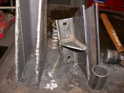
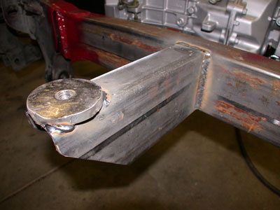
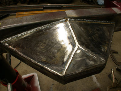
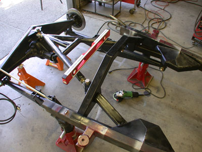
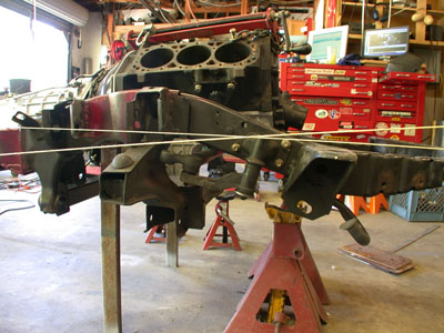
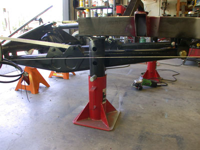
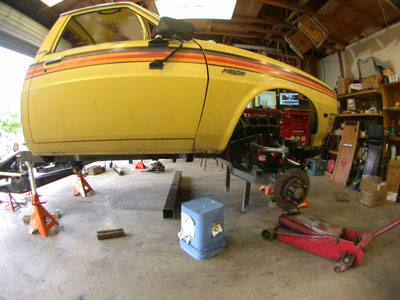
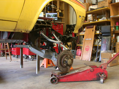
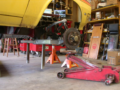
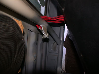
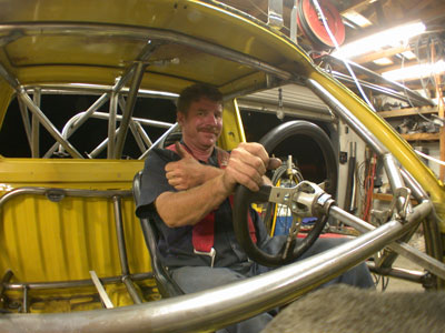
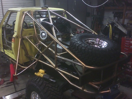
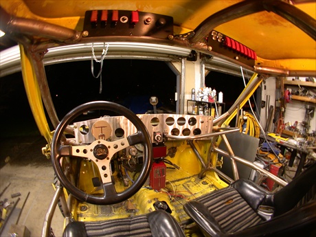
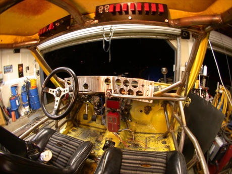
    Well the cab is now cleaned up and ready to start on the fabrication. I found a nice sharp air hammer bit trimmed the cab real easy. I just took my time and worked on the inside of a bend next to the line of spot welds or with a steel backer and she cut like butter. I cut out the inside of the doors in order to give my self 4 more inches of elbowroom in the cab. Once the roll cage gets started things get tight quick. I will start with the doors by using some square and round tubing to re-enforce the door skin. The whole cab can be picked up one person now. I would guess it’s around 185Lbs. I’ll try to get a weight on it before to long. Building the front suspension is going to be a little harder then I thought, due to the narrow with of the truck. I might be forced to widen and lengthen the wheelbase in order to accommodate the new suspensions. The doors are made stable again. I used 1 inch round tubing across the top of the door panels. Tacked it to the tubing across the top, then used ¾ inch square across the bottom of the door just under the door latch to the lower hinge mount. Added in ½ inch square tube between the two. I found that the ½ inch square fits nicely in the stock window channel. It makes it easy to weld to the back of the door just above the door latch. Just gives enough room to remove the latch. Once the roll cage is installed I will be able to put the inside door handle back in.


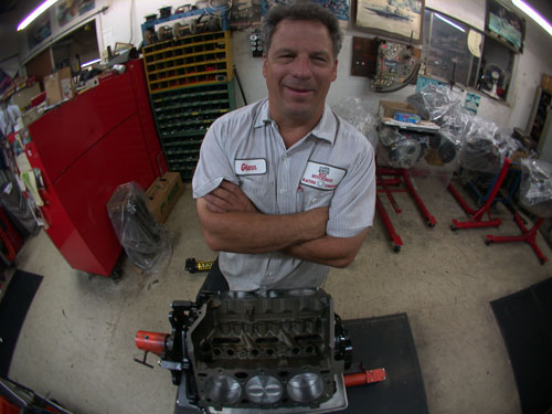
    Well I just picked up an early block 4.3L V6 it’s a 1992 out of a GMC Jimmy.
    She is one ugly suv. It came from my neighbor who owns Collage Oak towing here in Sacramento.


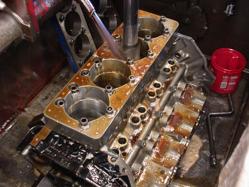
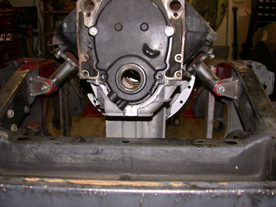
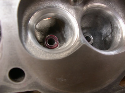
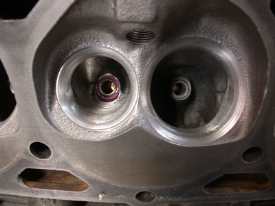
    It was over heated pretty badly. It melted the guts right out of the temperature sensor. Other than that it looks to be a good engine to rebuild. I now can see the real differences between the 1997 Vortec engine and the 1992 non-vortec. One difference is the balance shaft in the vortec.


    other differences are the hold down and guides on the roller lifters. Then there is the timing chain cover and bolt pattern. The oil pans are stamped steel non-vortec cast aluminum vortec.

    4.3_oil_pans.jpg


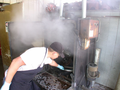
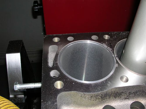
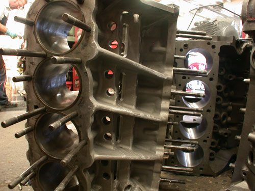
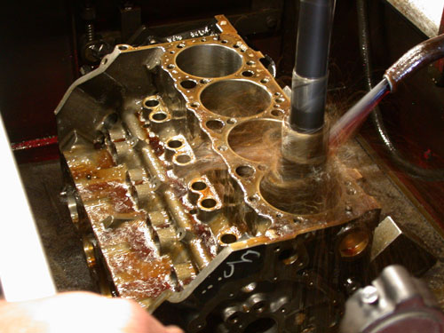
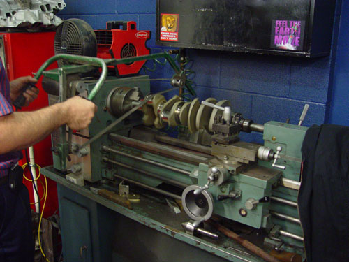
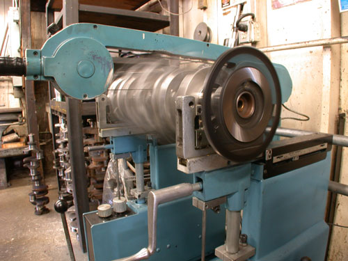
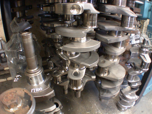
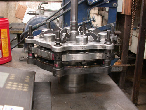
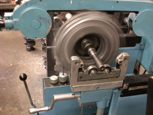
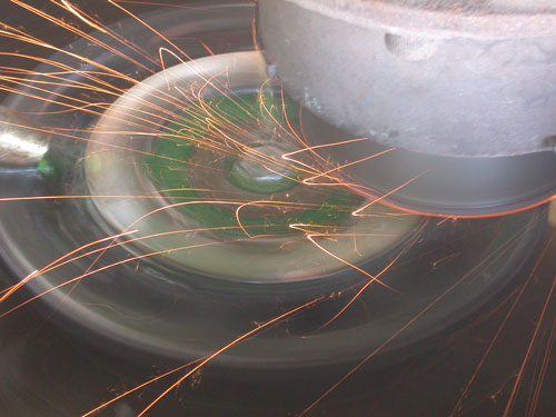
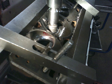
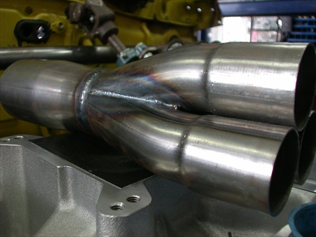
    The vortec came out of a Chevy S-10 the pan is about 1.5 inch taller. Looking at the back of the block the 97 vortec does not have freeze plugs in the bell housing area. The 92 block has a hole in the side for where a fuel pump would be mounted if it were carbureted. They just did not knock out the inner wall of the block casting. And of course there are the heads and the intake mounting bolts. Now I can use the Nascar manifold that is built for these engines. Oh and the Vortec engine had spun a rod. So it will make parts for the 92 if needed. Well I got the new older model 4.3 torn down and ready to go the machine shop. Every thing looks good inside this one. I should have pictures of the machine process when they get started on it. It will be a couple of weeks tell they get started on it.


    Last edited by camoit; 06-09-2019 at 04:18 PM.
    Members come and members go, But the board keeps track of them.
    Find me on FaceBook
    clicking HERE.

    Or look on YouTube Click Here.
    http://mobilemillwright.com

  7. #7


    Array
    Status
    Offline
    Join Date
    03-16-2011
    Posts
    3,803
    Location

    Sacramento, CA
    Vehicle

    1979 Dodge D-50
    Engine

    Chevy V6
    Well I picked up the crank from the machine shop today. It was tanked and checked for cranks. It looks to be stock. I brought it home and DE-burred it tonight. It took about 2 hours. It’s not a 32 Lbs crank but it is cleaner then just a cast. The machine shop has another 4.3L V6 there right now. It came out of a bush grand national car. The guy that owns it paid $18000.00 for the engine used. I’ll snap some pictures of it. It’s an odd fire unit. The estimate of the rebuild that they are doing sits at $14000.00. It will make 500 Hp when they are done with it. Here are some before and after pictures of my crank, along with a side by side of a stock crank.

    stock_crank2352.jpgcrank_debur2362.jpg
    stock_crank2354.jpgcrank_debur2363.jpg
    side-by_side2364.jpg


    Well I took the vortec heads over to Rex Hutchison Machine. There are 2 major changes between the Vortec and non-vortec heads. One is the intake mounting. The other is in the intake it’s self. The pictures below show the two set of heads I have. The NON-vortec head the intake airflow is directed in from the side of the valve. The air then swirls in to the piston in a counter clockwise direction. To add performance to this head you would grind out the ramp that is pointed out in the picture. Then you would open up the pockets in the bottom. This would take about 6 hours of labor on each head. That would cost $750 per head. The vortec head has very little that needs to be done. There is only a little pocket in the casting that needs to be cleaned up. I'll get some better picts these are from my phone.
    I have also included picts of the Bush engine they have.


    non_vortec_head.jpgvortec_head.jpg
    bush_crank.jpgbush_front.jpg
    bush_topend.jpg


    Update. Well the machine shop, Rex Hutchison Racing Engines should start the block work next week. The block is good but there was one little crack in one of the Vortek heads. I’ll try to get some pictures of the work. But in the mean time I decided to go ahead and buy a front-end kit instead of building one from scratch. It should save me around 4 weeks of design and 4 weeks of build time. I’m going with a kit from Total Chaos. So I went out and picked up front spindles from a 2000 Nissan Frontier 4X2 V6. The kit is right at $3000.00. On a stock Nissan the kit will give 13 inch of travel. This is limited by the stock bump stops on the lower part of the frame. So after talking with Total Chaos I should be able to get the 18 inches of travel I’m looking for. Now I just need to go get stock frame bushing mounts and elliptical cam adjusters from Nissan. It will take around four weeks to send out the spindles and have the fabrication done. Here is a picture of their kit and some pictures of the first VORRA race of the season here in Sacramento. The trucks in the pictures is using the kit I have on order. Except for the one that did an endo...


    91420_kit-s.jpg
    fullracefrontend.jpg
    fullracefrontend1.jpgfullracefrontend2.jpg
    VorraRace.jpg


    Just picked up the new front end. It is off of a 2000 Nissan Xterra. The suspension kit is ordered and should have it by May. I was able to order it direct from the builder. They are meeting a group of Vorra Racers and handing it off to them then it will find it's way to me. No shipping charge As for the cost so far here is what I have. Complete front spindles $400, frame $175, power steering box $200 long travel kit $3121. Total $3896


    New_front_end_frame.jpg
    Last edited by camoit; 06-09-2019 at 04:19 PM.
    Members come and members go, But the board keeps track of them.
    Find me on FaceBook
    clicking HERE.

    Or look on YouTube Click Here.
    http://mobilemillwright.com

  8. #8


    Array
    Status
    Offline
    Join Date
    03-16-2011
    Posts
    3,803
    Location

    Sacramento, CA
    Vehicle

    1979 Dodge D-50
    Engine

    Chevy V6

    The secret world of the machine shop.

    OK here is a rundown on the secret world of the machine shop. I just spent an hour or so here cleaning up some of my parts. Here are some things to keep in mind when talking to, and to looking for one to use. I’m using Rex Hutchison Race Engines.


    Rex Hutchison has been building engines since the flat head was king.


    One of the problems with a shop is the lack of time spent on an engine. When you take an engine to a shop take a look around


    and see just what kind of money is sitting there.


    I mean the type of engines and equipment. Is it just stock blocks or are there a 4 or 5 big money engines there under construction.


    With Rex there are engines that range from stock to 11000 Horse Power costing around $80,000 bucks or more.
    What are the steps your engine will go through. First thing that needs to happen after washing


    is to magnaflux every thing. For most places this is a standard practice. The two main types of testing is Dye and Powder.


    Now one big thing the shop must use is an ultra sound thickness gauge. They will need to take at least 2 readings. two measure the bore. Top and bottom.


    One problem with a block is there is no way to easily measure the wall thickness of a block. Before you bore a block you need to find out how thick the cylinder wall is. If you bore it over .030 you might have too thin of a wall and the engine can crack a cylinder or get hot spots when running. Once you use an ultra sound on the cylinder you can find the thinnest cylinder wall and rough size the bore accordingly. Making sure to have plenty of cylinder wall left.


    Just because a block has never been rebuilt doesn’t ensure that it is a good block.


    Next comes the line bore for the main bearings.
    Now comes the wet hone


    Normally they should be done in four steps. (NOTE the next picture has an adapter bolted on to keep the fine hone in line with the bore so you can get the top edge honed correctly.)


    This will put the cool little lines in the cylinder. These lines are very important. With out them the piston rings will never seat and will leak compression gas and oil. These lines must intersect at a 60-degree angle. During this hole process the cylinders must be repeatedly checked for taper and proper bore size. Bore size is determined by the new pistons that are going in and the ultra sound test. Here is one of my new pistons for my V6.


    You must hone out to the final size. This takes quite some time to get it right. Every time you go to a finer stone you must take out less and less material and sneak up on the final bore diameter.


    Onto the heads. Heads will always be checked for cracks. But if you are going for some power you will need the shop to port the heads. First they CC the combustion chamber then cut the deck or just check for twist depending on what compression ratio you want to get. Then we replace the valves and seats.


    Then we perform a vacuum test to check our work.


    Now they will work on porting and run them on a flow bench.


    So now it’s time to work on the crank. They will polish it if possible,


    if you had spun a bearing or lost oil pressure they must grind down the bad journal.


    Now it can be rechecked for journal run out.


    Last but not least of the fun stuff is the spin balance. In this step we must know a couple of things. First is the weight of connecting rod. This is combined with the weight of the piston and the rings. To simulate the pistons and connecting rods you clamp on these adjustable weights.


    Now we can spin it up to speed.


    During this test we can find out where the heavy spots are. There is a meter on the balancer that shows witch end of the crank is heavy and how high from center is the heavy spot. There is a strobe light that flashes on the crank so you can reference the crank to find the heavy spot to drill.


    We must not forget about the flywheel and pressure plate. If this is out of balance then all the work done on the crank was a waste of time and money. So give them all of your parts.


    One thing that they will do before starting to balance the flywheel and clutch is they should resurface the flywheel. Here is an 11-pound flywheel being ground. The small shiny circle about 1 inch wide is the surface for the clutch.


    Well it’s time to put in the cam and start to work on the valve train. One of the biggest things a shade tree mechanic will do is go out and buy the biggest roller rockers they can find then wonder why the engine runs like crap. When setting up the valves you need to get the correct rockers. The rockers must match the cam profile you are using. I just saw a guy bring his car to Rex and asked them to look at it. First thing wrong was the engine had no breather. It was running under a vacuum. Next they has 36 degrees of advance. They put in a cam and rockers on stock compression and heads. I hope this helps to clear up what a machine shop does or does not do.
    Last edited by camoit; 06-09-2019 at 04:21 PM.
    Members come and members go, But the board keeps track of them.
    Find me on FaceBook
    clicking HERE.

    Or look on YouTube Click Here.
    http://mobilemillwright.com

  9. #9


    Array
    Status
    Offline
    Join Date
    03-16-2011
    Posts
    3,803
    Location

    Sacramento, CA
    Vehicle

    1979 Dodge D-50
    Engine

    Chevy V6
    Well my block has been honed to the piston size.


    The new pistons are .030 over sized flat top. This should give me a final compression ratio of 9.50 to 1.


    Here is my new ceramic, 6 puck clutck disk. It took 2 weeks to build and ship in. It's a 10.5 inch 3.10 LBS


    I started burning wire tonight. The 2 X 4 box tubing is squared and tacked to the Extera front end. The roll cage will go fast.


    My crank was balanced today. Or I should say they started on it today. I just happened to show up there when Mike, the crank and head guy was working on it. He was having a problem with the balance. He was trying to figure out why the balance was so far off. Apparently the 4.3 V6 even fire engines have a built in unbalance to them. The odd fire is not as bad. The crank is a total of 180 Grams under weight. 180 Grams under is nearly un heard of. But then again this is a Chevy V6. There known as the little shaker. They did not have the right weights to finish the balance. They need to order them in. 5 days. One weight is in LA and the other they need is in Minnesota. I can’t figure out for the life of me why GM or any other manufacture would have an engine so out of balance that they need to have a counter shaft. If they would just balance the engine to begin with they would not need the horsepower robbing balance shaft. But I can only guess that it must be cheaper for the manufacture to just drop in the shaft and keep production rates high VS spending the extra time to do the job right the first time.

    If you look at the picture you can see the added weight simulators on the left and right of the crank. It’s a bolt with a copper weight on it locked between big counter weights.


    It’s parts day. I picked up my rear trailing arms. They will go over to the strippers then get a new coat of paint some new bushings and new uniballs.


    Here is the front end. I should be able to get about 14 inch of travel. It has uniballs with high misalignment spacers instead of ball joints.


    My new Quick Time bell housing from D & D transmission was the wrong one. It’s was for a Ford. So they are going to send me another one. Hope it will be right this time. I will replace the pictures with better ones soon.


    I now have a rear end. It’s out of 1995 Isuzu Rodeo. It has disk brakes. The gear ratio is 4.10 Dana 44. I put in a Limited Slip carrier in the unit. It’s an Auburn Gear unit. Part # 542083. Apparently the Rodeo came with an option for several types of gear ratios. One was a limited slip. These are quite rare to find. The brakes use a disk / drum design. The parking brake is a small drum brake inside the disk rotor. This is now pretty much a standard design for most cars now. Some other cars rear disk brakes had a mechanical lever on the caliper for parking. This type takes a special tool to “un wind” the caliper cup. Those suck to work on.


    I found a good local place to supply nearly all of the custom parts I need. They are called http://www.ruffstuffspecialties.com I went to there shop and picked up a couple of tabs that I needed to start to put the rear end together. I also changed the pictures of the front end page so you can get a better idea of how that works. And my bell housing arrived today. The correct one. Now I can put together my mock up block and build mounts. If you get a chance check out ruff stuff web site. They have adaptors that can be used to put disk brakes on a rear end. To make it fit a MM or D-50 there might be some additional work. But I would bet there is a smart guy on this board that can make the parts work. For all you “Air Bag” lovers out there, they have a large selection of trick tabs and weld on things for 3-link suspension. Including Heim joints of all size. They even have the parts to build tie rods with Heim joints.


    I put on the bell housing today. In the process of starting the job I took the bolts out of the package and found out that they are to short. Yes they are cool allen head bolts but they are ½ inch short. They only came out of the trany by 3 threads. I also discovered that the steel housing was tapped with worn taps. So when I check the bolt holes with the bolts that came in the package it was like putting a pipe plug in the hole. Sloppy until the bolt reached the last thread but to short to bottom out. So to over come this problem I used longer bolts. And to insure that they wont pull the threads I used blue LocTite and backed it up with a jam nut. Problem solved. Sorry about the fuzzy pictures it's a cell phone.


    Rear trailing arm up date. I was able to finish up the trailing arms today. I installed the new 1-inch Uniballs. Then I worked on the bushings. The new ones were to long by about 1/8 inch. So I needed to cut them down. After marking them with a black pen, I used a bolt and a nut as a clamp, then placed it in the drill press and spun it up and held a hack saw up to the bushing. This worked great. I was able to cut them down with in a whisker of what I need them to be. After cutting them I touched them up with a grinder and was ready to make the bushing center shaft. The shaft is made of .095 tubing cut to 3 inch. I used a square to true the ends up. Now it was time for the axel Uniball mounts. The Uniballs go down on the rear end. The brackets came from a local builder, Rough Stuff. So far all I had to do was make the hole into a ¾ inch. I will need to cut down the long one to get the correct angel for the 3-link suspension.

    Last edited by camoit; 06-09-2019 at 01:19 PM.
    Members come and members go, But the board keeps track of them.
    Find me on FaceBook
    clicking HERE.

    Or look on YouTube Click Here.
    http://mobilemillwright.com

  10. #10


    Array
    Status
    Offline
    Join Date
    03-16-2011
    Posts
    3,803
    Location

    Sacramento, CA
    Vehicle

    1979 Dodge D-50
    Engine

    Chevy V6
    Ok here is the new rear end. It’s a 1997 Isuzu Rodeo with a Dana 44. The first thing I did was to send it over to the stripers and put in limited slip. Then I cut off the spring perches.


    Next it was tine to build the truss for the 3-link suspension. When building a 3-link suspension you must keep in mind what the pumpkin is made of. If it was forged steel you could weld right on to it. But if it’s cast you had better stay away form trying to weld on it. Cast iron is pours. This means that there is little tiny air pockets throughout the casting, and you can’t weld anything structural to it. Because it will crack along the weld. So in order to build a rear end that will hold up to the riggers of off road, you can go out and spend $800 to $1000 bucks on a housing or just bridge over a stock rear end. Here is the 2X6 tube truss being fitted. I used a peace of cardboard, and cut a pattern that I used as a template to clear the pumpkin. Keep in mind that the under side of the tubing needs to be boxed back together, so leave some clearance around the dif.


    After getting it to where you like it be careful not to weld too much at one time or you will bend the housing. First tack it together above the dif. Wile it's clamped down to the housing. Then fully weld it off the rear end on the bench.


    Box in the underside of the truss over the differential. Once cool you can place it on the rear end. Now you will need to have a bucket of water and a rag. Put on some heavy tack welds to connect it to the housing. You only want to weld 1.5 inches at a time working around the housing in a diagonal pattern to keep twisting to a minimum. After welding each area, cool the weld with water until you can grab it and hang on. You want to keep things as cool as possible.
    Here is a picture of the new fabricated differential cover next to the stock one and a picture of the finished rear end.


    It’s been a busy week. It seems like every time I take one step forward missing or wrong parts take me back one step. Only one E brake cable came in. Then Nissan ordered the wrong bushings. They orderd front lower “A” arm not the rear. That’s even after I pointed to the correct one on his computer screen. Even after the problems I was able to get some things finished. The engine and trany is place and the body is centered on the frame.
    Here is the trany mount and the 2 X 4 square box tubing I made it out of.


    Now it was time to place the engine and center the body on the frame. But how do you figure where to place the body in relation to the “A” arm mounts, or even the engine and trany? Where or how do you start? Well here is what I did. First I would need to find the centerline of the front spindles. To do this I placed the upper “A” arms in the frame then ran a string between the two. I then marked the frame with a pen then used a peace of tape and used silver paint to make a permanent mark. You can see it in the picture below.


    Now I can measure back from that line, the distance from the spindle to the cab on my other truck and apply this to the new build. From there I dropped in the engine and trany. Once I found the sweet spot for the shifter I raised it up to its final height in relation to the cab. Keep in mind that the cab must be raised off the frame rails. After securing the engine and trans with a jack stand and floor jack we lifted the cab back off. Now I centered the engine and trans to the frame. It came out with in 1/16 of an inch after building.


    Finely it’s time to bend some tubing for the trany mount. It’s been 12 years since I last ran my tubing bender, I hope I don’t make to much scrap metal.


    Now that the trany mount was welded it was time to put my helper to work. This is Nate. He is 20 years old. He is my neighbor’s son. He has been doing manual labor things off and on around my house since he was 17. I finally have him trained enough to turn off the phone, listen to what I want done, and show him once. He can normally get it done with out too much guidance. Today was his first day of fabrication and mechanic training. Righty tighty, lefty loosy is a new concept for the boy. He will get it in a couple more days.


    Once Nate got the parts cleaned up with the Tiger Paw it was time to do the final fittings. The trany mount worked out just fine. It didn’t change shape, or didn’t need to be forced into place. She matched right up to the trany and mounts. Now the engine and trany are sitting in the frame.


    As some of you know there is now a live video feed from my house on the build, where you can see and here what is going on. If you haven’t seen it yet go and take a look. I have worked out most of the bugs but there is still some fine-tuning left to do. I want to create a code that can load onto the board, so that when you click the link it will open an other browser or just a pop up with the player in it. You need to use Internet Explorer to see the video feed. I’ll work on that soon. You can find a link under the photos and media section. Or here. CLICK HERE FOR FULL SCREEN LIVE FEED This will open up your Windows player. This ends the problem that others were having.


    Well the last couple of days have been real busy so I guess it’s time for an update before I get to far behind. During this time I was able to get the cab mounts done, find and set the wheelbase, square the rear end, and get the rear trailing arm mounts built. First up was the cab mount. I was thinking of reusing the stock ones but that turned out to be a waste of cutting gas and time. So I built the new ones out of 2 X 4 box tubing with a ¼ inch thick plate steel washer on top of it. I currently have the cab configured to use some ¼ inch rubber as a sandwich below and above the cab. This may change during the build to a taller designee for clearance reasons so I saved my old rubber mounts. Well part of them.


    First I need the washers from the stock mounts. They will be used on the inside of the cab. If you go out and look at the stock mounting bolts, you will see that the cab is held down by some very small bolts. Lucky for us that the whole cab is only about 150 pounds. Including the front. My cab is somewhere around 120 pounds. With two guys you can lift it above your head.
    Here is an easy way to remove steel parts from rubber. Just use the Propane torch.


    Now I found a neat trick to drilling a hole in rubber. Everyone out there at some point has tried to drill a clean hole in some rubber with a drill bit. Just to discover that it is a pain in the ass. There are some special tools just for drilling in rubber but there hard to find and pricey. So first I used a standard whole saw to cut the large diameter. This has worked great for years. But I need to make a clean 5/8 hole in the center. My salutation was a flat wing bit for wood. The ones I used have a small tang on the outside edge. This made a nice round circle before the flat cutter removed the center mass. WOW this worked better then a Government oil well plug. And made a clean hole to boot.


    Here is the rear trailing arm mounts. Now it’s time to work on the pinion and “U” Joint angles between the trany and the dif. The mounts are 2 X 6 box tubing that has been internally gusseted and top gusseted.


    The rear end is now finished. Here are just some of the things to keep in mind when doing a 3 or 4-link suspension. Here is a good reference to help you decide how to set up the rear end of your truck. It’s a long read but the information is put together well. Please reed some of it befor going on to the lower part of this section. Some parts from the other site will help you with the fallowing pictures.http://www.sporttruck.com/techarticl...ign/index.html


    Now for my truck I need to keep a long travel and be able to make it drive like a raped ape on the street. So the first thing I did was square up the rear end. Then build the 3rd link. Now I need to find the Instant Center.


    This is what will determine how much the truck will rise in the rear, under heavy acceleration. At first the wishbone was set to high over the frame. This put my instant point too far out in front of the truck. This meant that the back of the truck would lift during heavy throttle. So I lowered the front of the front of the wishbone by 4 inch. This moved it to the front of the engine and put it right around the camshaft at ride height. At this point it should give me a roll center right around my seat bottom. One thing to keep in mind is that you always want to put torque to the same point. I ran my upper arms to the cross member then added square box tubing to the lower trailing arm mounts.


    The way to find the Instant center is to put a line through the lower trailing arm and upper link arm. Extend the line until they meet at some point. This point is the instant center.


    NOTE The string lines show how torque is transferd through the frame to the instant center.


    Now here I lifted the truck up to the ride height. It sits at 24 inches.


    From this point I started to work on the shock angles and shock length I will need an 8-inch shock for the front. The front end gets 12 inch of wheel travel. While the rear end gets 18 inches of wheel travel while needing only a 12-inch shock.

    This is the front suspension from full droop to full bump stop.


    Keep in mind that when the Beer starts the work stops. So don’t let a one eye guy into your shop. You are just asking for trouble.
    Ron and my dog J.D. AKA: Jane Doe


    Last edited by camoit; 06-09-2019 at 01:30 PM.
    Members come and members go, But the board keeps track of them.
    Find me on FaceBook
    clicking HERE.

    Or look on YouTube Click Here.
    http://mobilemillwright.com

  11. #11


    Array
    Status
    Offline
    Join Date
    03-16-2011
    Posts
    3,803
    Location

    Sacramento, CA
    Vehicle

    1979 Dodge D-50
    Engine

    Chevy V6

    Welding and my shop area.

    I guess it’s time for an update. The temperature is a warm 98 today. So I will just get caught up on the build until it cools off. The main part of the cabin is near complete. I have the seat mounting bars set in place, and the seat belt bars are in. For the guys that want to use a 5-point harness in your truck there are basic things to keep in mind about belts. First use a 3-inch belt. Avoid the 2-inch belt at all cost. They can do more damage to you in an accident then the stock belt. It comes down to simple weight distributions. The more surface the better. A 2-inch belt will bend into taco shape and now you have a ¼ inch rope for a belt. Not a good feeling. This is why they have banned them in nearly all forms of racing. Second DO NOT mount the shoulder belts above the Scapula of your back, Or shoulder blades. If it is to high then you can crack your spinal cord or sever your head during a crash. This would make for a good story on the 5 PM news. Head flies off during roll. Witness says, it looked like he said “holey shit” as it flue over. During a crash you can experience up to 165Gs of force. So keep in mind a seatbelt must not be pinched or have anything that can cut it with in 2 inches of it at all times. You should also think about the direction of forces applied to it. Keep bends and curves flowing not sharp.


    Now here is the main cab structure with some gussets installed. The cross bracing has yet to be installed. So far I have used 60 feet of 1 ½ inch .095-wall tubing and 20 feet of .120 wall tubing just to get this far.


    I have had a couple of people ask what it takes to build a good roll cage. Well here I go.
    If you want to build a cage for your truck there is some tools you will need. First is the welder. Go out and find a good 220 Volt mig welder. You can use Argon Co2 mix or just Co2. Don’t use flux core. Straight Argon is for Aluminum I have used Co2 for many years and have just become accustom to how it works. A large tank can last me up to 10 years or more at home. I just replaced one of my tanks after 15 years of use. It went through 5 of the big rolls of .030 wires. Co2 burns hotter than Argon mix and you can burn through thin wall steel. It just takes time to get good. I will get into welding later on.


    Now you need to find a mandrel bender. DO NOT get a pipe bender. There are some ratcheting low cost ones that work OK and make nice bends. You can find them here.

    http://www.tubing-benders.com/?gclid...FQ4iawod4Gxx3A

    But if you really want to do the job right then you can expect to spend around 1200 bucks for a good quality tool. Here is a good source for tools and lots of other things you will need to do the job. Keep in mind if you buy something good you only need to buy it once. They still make and sell the tools I picked up back in 1997. You can get a low buck tubing notcher.
    http://www.irvansmith.com/scart/index.php


    Now when it comes to tools you get what you pay for. I have spent the last 20 years filling up my box. Yard sales, auctions things like that. I set a goal and then collect parts until I have enough to get going on it. Here is my garage and some supplies that people have tossed out that I have found over the years. My nut and bolt collection was a major score.


    Now lets talk a little about welding.


    "When welding tubing you need to keep an eye on the fit of the tubing." If you have a large gap then you will “burn through” You can fill the gap but it takes time and every time you start and stop the fusion of the metal you take a chance of O2 getting into the weld and producing a pimple or “zit hole”. If you have the gas flow up to high wile using Co2 you can over heat the steel. I run around 12 Cubic Inch Hour. At this rate I can get a good Spray of metal. There are times when it can be an advantage to use a Globular transfer method, manley when filling a large gap between to parts. If the gap is large or the parts are thin there is the option to noodle weld.


    Make the fit on your tubing as tight as you can. Spend the extra time and do it right, there is no shortcut in frame building. Remember the forces that will be applied to the cage.


    Let’s talk about getting heads ported. My heads have been ported and are ready to be assembled. You will have many people tell you about valve seats and angles. 1,2, or 3 angle grinds. But when you look to improve performance you only need to look as far as the first 2 inch down the ports. Most improvement to air flow is right below and next to the valve. The head on my engine is within .020 of the intake gasket hole and the intake manifold porthole. When it comes to porting a head you need to open up the area right below the valve seat. The exhaust valve seat and valve has a radius seat. Not an angle cut. This allows for better flow of gas out of the combustion chamber. The intake has a 3-angle grind. This allows for a better seal so combustion gases can’t escape into the intake and cause a backfire.


    One thing I have seen people do is put larger valves in to a head. This can create larger problems and is more costly to do. The only time you need larger valves is if you are building a blown engine or top fuel car. But if you are dead set on larger valves then just go out and pick up heads that are built with them. It will save you in the end. One thing you should do is look to see how close the valve is to the wall of the combustion chamber. On some heads the valve is very close. So by just clearance that area you can greatly improve the flow. Here is a head that has been clearanced to allow for greater flow. It was opened up by .050 that may not seem like a lot but when you deal with 1000s of an inch it is a lot.


    Rear frame is now DONE..........

    Last edited by camoit; 06-09-2019 at 02:28 PM.
    Members come and members go, But the board keeps track of them.
    Find me on FaceBook
    clicking HERE.

    Or look on YouTube Click Here.
    http://mobilemillwright.com

  12. #12


    Array
    Status
    Offline
    Join Date
    03-16-2011
    Posts
    3,803
    Location

    Sacramento, CA
    Vehicle

    1979 Dodge D-50
    Engine

    Chevy V6

    engine specifications

    The machine shop started on my engine today BUT then they called me to confirm some information. The final decisions are are now made for the engine. 500 cfm carb. 6000 RPM redline. 6800 RPM free spin. Revlimiter set to 5700 RPm. Power band from 1500 RPM to 5000 RPM. Now with that change the cam profile changed from the first idea of using fuel injection. Larger selection of cams. So now with the new cam comes diferant roler lifters. Diferant valve springs. And gear drive. ARP head studs and rod bolts. 7 QT oil pan. Millings high volume oil pump. I don't want to spend another $4200 to dry sump it. But that would give me another 50 HP and push it to 400 HP. 27 LB lightend fly wheel. Flat top pistons 9.7 to 1 compression. Port and polish job, Raidous exhuast valve grind, 3 angle intake grind. Mainfold port and angle matching. Roler rockers. Custom leingth chrome alloy push rods. I will put together a full speck sheet when the engine is done along with a price sheet.


    Time for the engine update now that’s it’s built.

    Here is my engine builder Glenn Hutchison. He has been working for his dad and building race engines for nearly 30 years.
    The business is located in Sacramento Ca. If you want to have them build you an engine don’t be in a hurry. The big race engines come first unless that’s what you want and can spend. They can be reached at 916-483-9563.


    They have engines shipped to them from all around the globe to be built up. They curently have 4 big blocks in from Australia. They run around $80,000 to rebuild. Since I didn’t have that kind of cash to burn I just let them do there thing at there owne speed. It shows in the work they do. My block was clean enough you could eat off of it.


    Here is the long awaited engine specifications for the Chevy 4.3 L V6.
    I used a 1992 GMC Jimmy 4.3L V6 early model block. No counter shaft on the early model blocks. The heads are 1997 Vorteh heads.

    We will start off by telling you that the exhaust valves have a radius cut. This improves the flow. The pockets have been ported and polished out. The intake and heads have been port matched. The intake flange angles have been matched to the heads. The intake valves now have a 3 angle grind.


    Specifications:
    Comp Cam
    Part Number: 09-430-8 Grind Number: C43 280H-R10
    Lifter Type: HYD. Roller
    Engine Family: Chevrolet 4.3 liter 262 c.i. 90° 6 CYL. 1980-1997
    Description: Hydraulic Roller-Limited high performance street use. Needs intake, headers & stall, 3.73 to 4.10 gears. Mild rough idle.
    Cam Family: Magnum™ 1987-Present Originally Equipped With Hydraulic Roller Camshafts, NON-BALANCE SHAFT
    Specifications
    RPM Range: 2000 to 5500
    Valve Timing: 0.006
    Lobe-Center Angle: 110
    Intake Center-line: 106

    Intake Exhaust
    Valve Lash: HYD. HYD.
    Duration: 280 280
    Duration @ .050" Lift: 224 224
    Valve Lift: 525 525
    Lobe Lift: 352 352
    Valve Timing @ 0.006 Lift:
    Exhaust Closes 26 ATDC Opens 74 BBDC
    106 Center-line
    Intake 34 Opens BTDC 66 Closes ABDC


    PRW Race Roller lifters.
    PRW 350 Stainless Steel Roller Rockers.


    Block Bore Dia. 4.030.
    Cam Gear Drive.


    Crank Saddle Bore Dia. 2.641.
    Federal Mogul TWR Forged Piston.


    Chamber VOL. 62cc.
    Comp Ratio 10.1:1.
    Rings Perfect Circle 40564 CP .030.
    Rods are stock.
    Duel Head Springs MFG.Ed Iskenderian #6005.
    135 LBS. Press.
    ARP Rod Bolts and Head Studs.


    Edelbrock Intake #2111.
    Edelbrock Carb 650 CFM 4 barrel EDL-1806.
    Edelbrock Carb Spacer # 9266.

    MSD #6430 Ignition MSD 6TN/6ALN NASCAR CD Ignitions.
    MSD #8597 Ignition – MSD Pro-Billete Distributors.
    MSD #8680 – MSD Adjustable Timing Control.
    MSD #8252 Ignition Coil, Blaster HVC, E-Core, Square, Epoxy, Blue, 42,000 V,

    Champ Oil pan.
    Millings High Volume Oil Pump.
    HP 350.


    Now on to the rims, brakes and stud problems. I would like to thank every one that voted on the rims. Well you said to get the ones with the larger holes and that is what I did. The first problem was the studs. With the new aluminum rims the stock studs were too short. So off I went to the parts store with a vernier caliper and 1 stud from the front and rear hubs. After several hours I found some that would work. The front ones were a direct replacement with no modification. But the rear was another story. The rear is now a 1997 Isuzu Rodeo Dana 44. The new studs were the correct length I needed but the shoulders were to long. So I had to grind them down to allow the brake rotor to lay flat on the hub. The best way to grind them down evenly was to put them in them in the drill press chuck and spin them while I hit them with the grinder.


    Now to make sure that the rotor was seating all the way down flat on the hub I used my paint pen. I made some marks on the hubs and then placed the rotor on the hub. If it seats the paint will transfer to the rotor. I had 1 or 2 studs that did not allow the rotor to lay flat. So I then used a counter sink bit to take off just a little bit from the inside of the rotor around the stud holes. Keep in mind that rotors are made of some soft material so its easy to remove to much real quick. Installing new studs is easy with a lug nut and some washers. Just use the impact gun and they go on real fast with no banging of the hammer or chance of shocking bearings.


    Parking Brakes.
    This was a challenge in it’s self to figure out how to connect a 1980 D-50 parking system to a 1997 Isuzu Rodeo. I was able to use the stock parts for some of the transfer. Parking lever, cable and mechanical leverage with saddle that is located under your truck. I did need to flip the mounting bracket upside down to accommodate the new trany mount and location. Next was the process of attaching the Isuzu cables to the intermediate cable. I had to have a cable made up that you'd give me lots of adjustment in three places. Then I had to figure out how to connect the adjusting ends to the Isuzu cable ends. Isuzu uses some hammer head style cable ends. So how do you go from this to a threaded rod end? Well the best thing I could come up with is what you see here.


    This is not the finished product. You want to pull a cable in a straight line when ever you can The finished part has a 90 degree off set to alien the cables. I used a peace of solid rod that I threaded to receive the new cable ends. The Hammer Head ends worked them self out with the use of two frame gussets. This made for a nice clean clamp that could not let go of the ends when torqued down. More pictures on the brake system to come. Please look back later for an up date.


    Exhaust System is built..
    exhuast_wraped.gif


    The truck went to the Header and exhaust shop over the last two weeks. I took it to a guy called “Dom”
    His web site is http://www.dgheaders.com
    Dom and his dad have a shop in Auburn Ca. called M & M Mufflers.


    Him and his father have been building header for drag boats and Salt Flat cars for years. Here is there car they drive in Utah. The last time they went they broke the rear end at 165 MPH and spun the car around but it did stay up right,,,, this time.


    The headers had to be split into single tubes to allow for removal from the truck. Each header tube 34.25 inches long, then run down to the 3 into 1 collectors. Here is the left header under construction.


    It was a two week fight to get the system to fit the truck. He was hopping to run a single pipe system but that had to be changed to a duel system. Due to the lack of space and all the moving parts of the 3 link rear end. There was just no way to get it over the rear end, and keep it out of the way. Here is the finished system. Next it goes out for the ceramic coating guy. This should make for some interesting pictures. I have no idea how what the process is.


    Last edited by camoit; 06-09-2019 at 03:47 PM.
    Members come and members go, But the board keeps track of them.
    Find me on FaceBook
    clicking HERE.

    Or look on YouTube Click Here.
    http://mobilemillwright.com

  13. #13


    Array
    Status
    Offline
    Join Date
    03-16-2011
    Posts
    3,803
    Location

    Sacramento, CA
    Vehicle

    1979 Dodge D-50
    Engine

    Chevy V6
    Time for a quick update.
    Here is the KRC Pully system and power steering pump. The water pump is a Stewart stage 4 water pump. It pumps 120 GPM @ 48 PSi. I need the high volume and pressure to pump the water to the radiator located above the engine and in the rear of the truck. The High PSI is to break through any stem pockets that may rear there ugly head when running it hard.


    Here is the installed 4 inch Air Bump stops on the front end. The Fox Bump Stops will be pressurized some where around 250 PSI with Argon. Why Argon? Argon has a larger atom then Nitrogen and is a true inert gas unlike Nitrogen that is really close. Nitrogen causes the oils in a shock to foam. But it is less expensive. But since I have Argon I'll use it. Other wise I would need to get a tank of Nitrogen.


    This is the front end at full bump. I limited the front to 13 Inches of wheel travel on the front end.


    Here is where the spare tire will be located on the back of the truck. I only took about 6 hours to come up with the final location. I had to work it around the battery's that are located directly under it. The Radiator is a CBR 3 core duel pass 16" X 32" It is rated up to 1100HP for BTU displacement. It also has duel electric fans.


    Time for a quick update. I got the dash finished up and have started on the electrical.
    The dash turned out OK for not having a break. I used 2 chunks of angle iron in a vice. Then pushed very carefully. I used my Di-grinder with a surface prep disk on it to make it shiny, then gave is a clear coat and called it done. Now the gauges will cost around $1800.00 to fill all the holes. The gauges to be used are. Oil Pressure, Oil Temp, Water Temp, Water Pressure, Volt, Fuel Level, Fuel Pressure, Wide Band Air Fuel Ratio, Tach. and hour meter. Blow is a video of the gauges in action from Auto Meter.


    Lay Out


    The Brake Bias allows me to adjust front to rear bias control on the fly.
    Turn the knob to the right = more front braking. To the left = more rear brake.
    The Timing control allows for change in fuel Octane and altitude with out having to adjust the Dist. Turn it to the right = More Advance.
    The line lock allows for front brake lock up.

    Raw Dash


    Finished Dash


    After receiving the gauges I discovered that the drawing I received from Autometer was incorrect. The mounting thumb screws hit the dash top. So I had to use a block and dolly to make a step in the top. So now it's black.


    08-04-11_1603.jpg


    Last edited by camoit; 06-09-2019 at 04:04 PM.
    Members come and members go, But the board keeps track of them.
    Find me on FaceBook
    clicking HERE.

    Or look on YouTube Click Here.
    http://mobilemillwright.com

  14. #14


    Array
    Status
    Offline
    Join Date
    03-21-2011
    Posts
    767
    Location

    WA
    Vehicle

    1989 Mitsubishi Mighty Max
    Engine

    4G63-T
    Yo marty, theres a few pictures I havent seen before on this thread. Interesting that I missed em cause I like pictures. Lets me overlook the words. Lol.

  15. #15

    Array
    Status
    Offline
    Join Date
    03-26-2011
    Posts
    409
    Location

    Portland, OR
    Vehicle

    1986 Dodge Power Ram 50
    Engine

    G54B
    Would still really love to see some pics of how the old dash came out, and how you boxed in the new aluminum. It's just sexy as all hell, frees up space a s**t-ton, and...did I mention sexy?

    More than capable in the metal fab department, and my uncle does it for a living if I need access to anything special (press brake, punch, etc).

    Been thinking more and more of a black anodized dash!

    Hard to believe that thing started life as a D50, awesome job on it.

  16. #16


    Array
    Status
    Offline
    Join Date
    03-16-2011
    Posts
    3,803
    Location

    Sacramento, CA
    Vehicle

    1979 Dodge D-50
    Engine

    Chevy V6
    To remove the dash here is the manual. It starts on page 23.

    http://www.mightyram50.net/d-50/Fact...HEET_METAL.pdf

    Here is how it mounts. Not pretty but it holds solid. I built the hold dash with out a brake or shear. If I had that it would have saved me time. But it turned out OK for using the vise and 2 peaces of angle iron. I need to order my intercom. It will go on the far right of the dash and hook up to the CB and phone.

    I have 2 of the 6 shocks on order, I have the
    2.5 inch rear coil overs coming. Should be about 4 weeks.

    The bypass shocks I want to use are Piggy back as well. But if I need to I will use the remote reservoir units.
    Attached Images
    Last edited by SubGothius; 01-24-2023 at 01:18 PM. Reason: Fixed broken link
    Members come and members go, But the board keeps track of them.
    Find me on FaceBook
    clicking HERE.

    Or look on YouTube Click Here.
    http://mobilemillwright.com

  17. #17


    Array
    Status
    Offline
    Join Date
    03-21-2011
    Posts
    767
    Location

    WA
    Vehicle

    1989 Mitsubishi Mighty Max
    Engine

    4G63-T
    Wow. Still more suspension work? Are you on schedule for the summer first engine startup?

  18. #18


    Array
    Status
    Offline
    Join Date
    03-16-2011
    Posts
    3,803
    Location

    Sacramento, CA
    Vehicle

    1979 Dodge D-50
    Engine

    Chevy V6

    The Question?

    Now here is a question for you. How should I make my hood open up. Keep in mind that it will be a one peace fiberglass hood. I'm sending it out to the body guys ASAP.

    It will not look the same as what you see here. It will be totally different when finished. This will give me an idea on how accessible it will be. I love the look of the front tilt but then it's a pain to get to the front of the engine to change a belt. So I'm leaning toward the rear tilt. The rear tilt will have 1/8 fenders only attaching to the cab area.


    Last edited by camoit; 05-22-2011 at 10:57 PM.
    Members come and members go, But the board keeps track of them.
    Find me on FaceBook
    clicking HERE.

    Or look on YouTube Click Here.
    http://mobilemillwright.com

  19. #19


    Array
    Status
    Offline
    Join Date
    03-26-2011
    Posts
    674
    Location

    Stafford, VA
    Vehicle

    1995 Mitsubishi Mighty Max
    Engine

    Chevy V8
    man that is some really nice work. i dont even know what to say.

    glad to see it come this far. have the fornt tilt back....its alot easier to access... a few buddy's have dont this on there bronce 2 and few boggers they have.

  20. #20


    Array
    Status
    Offline
    Join Date
    03-21-2011
    Posts
    767
    Location

    WA
    Vehicle

    1989 Mitsubishi Mighty Max
    Engine

    4G63-T
    I say make it pop up like the jeeps but more stable connections. Also detatchable hinges. So it can come off completely. Tilt for easy access and removable for convinience.

  21. #21


    Array
    Status
    Offline
    Join Date
    03-26-2011
    Posts
    674
    Location

    Stafford, VA
    Vehicle

    1995 Mitsubishi Mighty Max
    Engine

    Chevy V8
    Quote Originally Posted by 4doorciv View Post
    I say make it pop up like the jeeps but more stable connections. Also detatchable hinges. So it can come off completely. Tilt for easy access and removable for convinience.
    yeah that is very common on some boggers i have seen....looks awesome too...

  22. #22


    Array
    Status
    Offline
    Join Date
    03-21-2011
    Posts
    767
    Location

    WA
    Vehicle

    1989 Mitsubishi Mighty Max
    Engine

    4G63-T
    I keep having to take off the hood to work on my truck. It's so much easier to work on it without the hood or the hood prop in the way.

  23. #23

    Array
    Status
    Offline
    Join Date
    04-01-2011
    Posts
    155
    Location

    Garden Valley, CA
    Vehicle

    1990 Mitsubishi Mighty Max
    Engine

    6G72
    are they gonna be bulged fiberglass fenders? if so how much of a bulge is there gonna be?

  24. #24

    Array
    Status
    Offline
    Join Date
    03-26-2011
    Posts
    409
    Location

    Portland, OR
    Vehicle

    1986 Dodge Power Ram 50
    Engine

    G54B
    If it's fiberglass? Carriage pins and fast complete removal. Ditch the tilt. OR, do the carriage pins thing with hinges to the rear. That gives you a choice - tip it or pull it. Fast either way and easy to fab.

  25. #25


    Array
    Status
    Offline
    Join Date
    03-21-2011
    Posts
    767
    Location

    WA
    Vehicle

    1989 Mitsubishi Mighty Max
    Engine

    4G63-T
    I like this idea. ^^^^^ You watch a lot of dakar rcing?

Page 1 of 7 123 ... LastLast

Tags for this Thread

Bookmarks

Bookmarks

Posting Permissions

  • You may not post new threads
  • You may not post replies
  • You may not post attachments
  • You may not edit your posts
  •